Valve flow control hydraulic adjustable line variable valves Parker hydraulic flow control valve, 3,000 psi, 6.0 gpm, steel Hydraulic control flow hydraulicspneumatics system
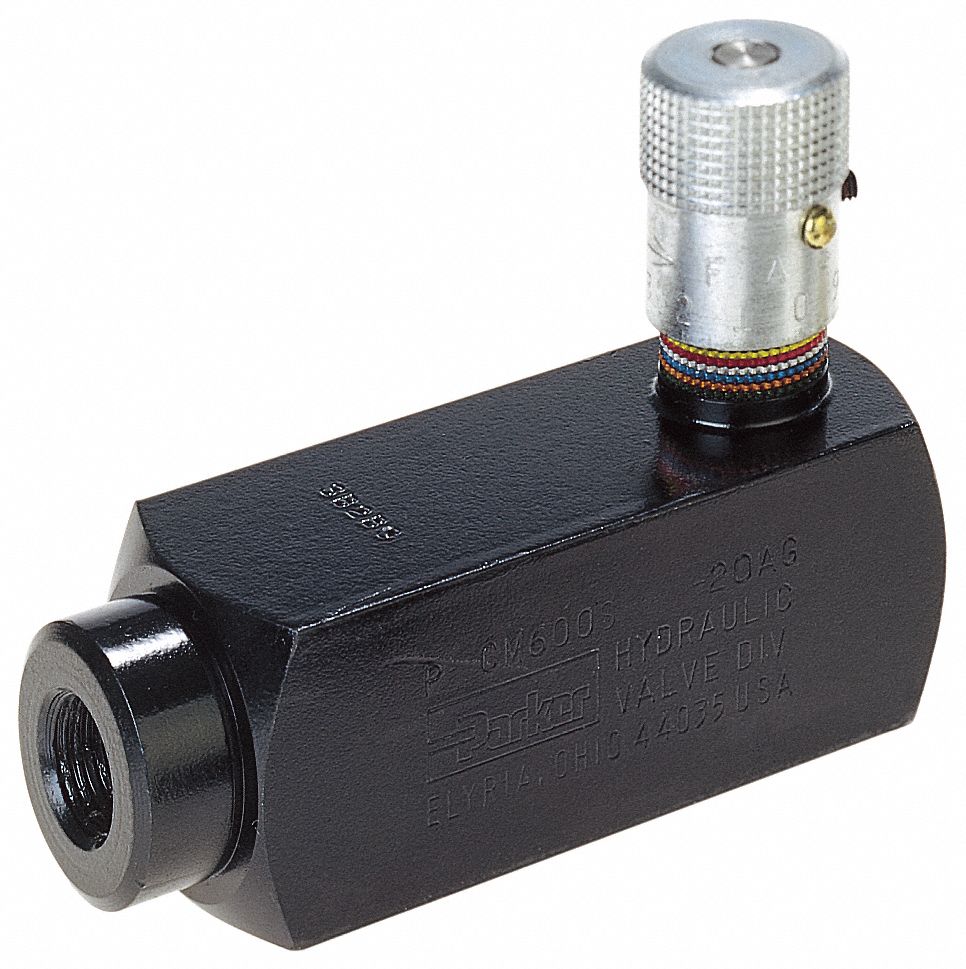
Hydraulic In-Line Adjustable Variable Flow Control Valve, 1/4” NPT
Flow control hydraulic valves pressure compensated circuit symbology controls
Hydraulic flow control valve 1/2" bsp ports 5 spool double acting 50
Flow control valve hydraulic valves symbol diagram system pressure compensated parker wayValve flow control adjustable electronically gpm brand hydraulics psi model hover zoom over Patents hydraulicHydraulic in-line adjustable variable flow control valve, 1/2” npt.
Flow control valve hydraulic pressure compensated schematic troubleshooting valvesHydraulic flow control valves – hydraulic schematic troubleshooting Hydraulic flow control valve w/ free reverse flow, 1/8" npt portsWhat’s the difference between hydraulic circuit symbols?.

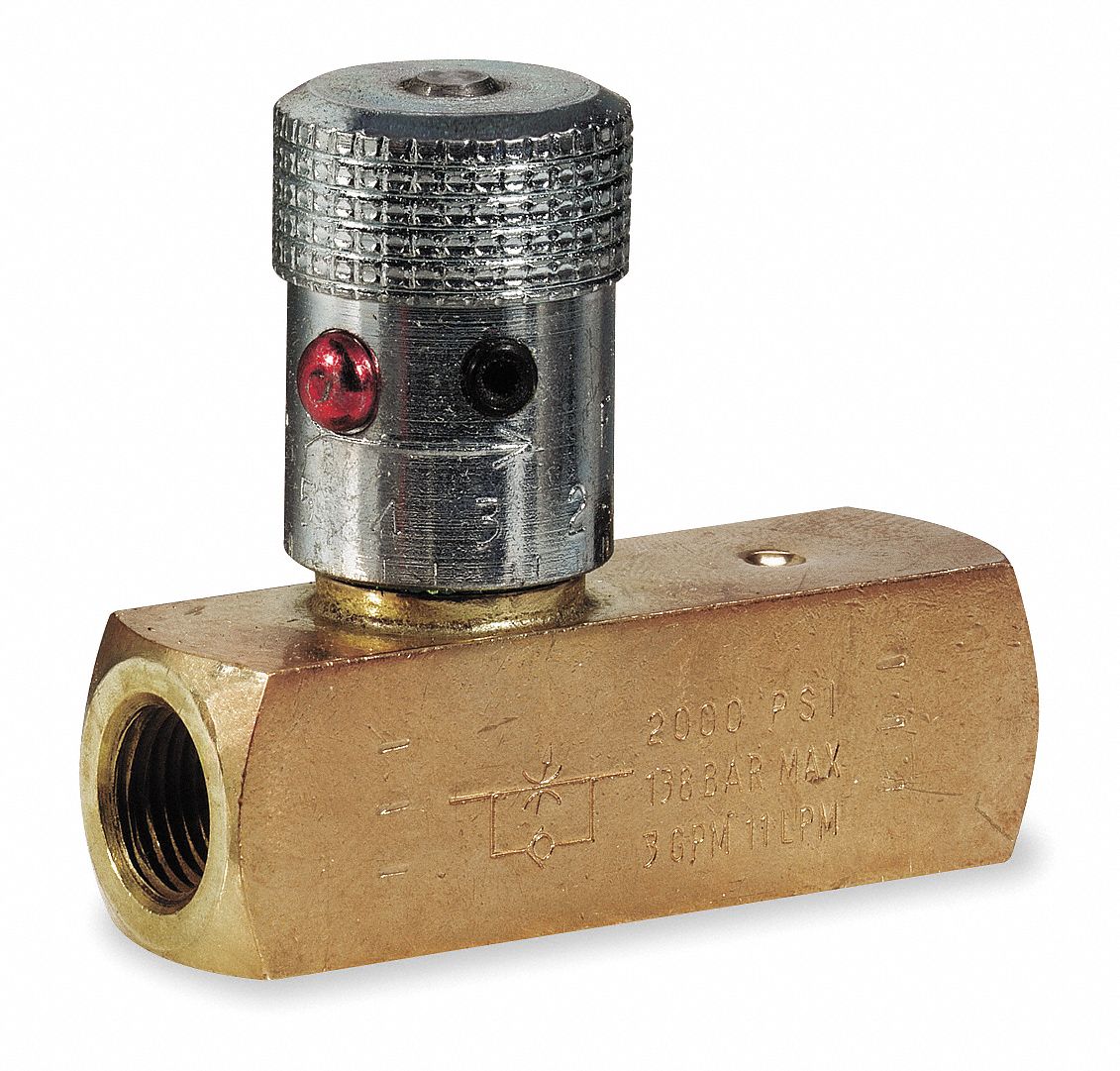
Hydraulic in-line adjustable variable flow control valve, 1/4” npt
Parker hydraulic valve flow control brass gpm npt grainger psi valves hannifin 2000 over zoro colorflow octopart steel rp zoomFlow valve control hydraulic parker grainger psi gpm zoom roll over Hydraulic adjustable variable flow control valve w/ relief, 0-30 gpmBrand hydraulics electronically adjustable flow control valve – 0–55.
Parker, 8 gpm max. flow, 5,000 psi max. pressure, flow control valveElectro-hydraulic system regulated by proportional directional valve Parker hydraulic flow control valve, 2,000 psi, 8.0 gpm, brassValve proportional schematic control hydraulic began progress idea.

Flow valve control hydraulic adjustable reverse npt valves variable line summit ports
Figure 1-12. click on image for larger view.Valves pressure technician meteran Flow control valvesPressure compensated flow control valves valve hydraulic diagram schematic orifice.
6 best images of mount hydraulic pump schematic diagramHydraulic directional system proportional regulated Flow control valve hydraulic variable line adjustable nptHydraulic system drawing circuit symbols diagram engineering simple beginners pump cylinder solenoid fluid mechanical valve hydraulics actuators symbol hidraulica systems.

Basic hydraulics
Hydraulic valve flow controlFlow valve control psi hydraulic pressure gpm parker steel compensated nptf valves colorflow grainger zoro hydraulics Valve hydraulic proportional electro control flow china sensitive sharing loading 100lWhat is the function of a control valve in a hydraulic flow system?.
Control valves workings hydraulicsProportional electro-hydraulic flow control (and check) valves Valve flow control hydraulic adjustable variable npt line gpm hydraulics fc51 valves summitHydraulic flow control valves.
Electro hydraulic proportional valve, loading sensitive flow sharing
Valve flow control hydraulic diagram pressure compensated operation parker valves bobcat dcv two hannifin permission reprinted 31b showing figure auxiliaryHydraulic circuit with 2-way flow control valve Flow npt rev[diagram] hydraulic flow control valve diagram.
Valve flow control adjustable hydraulic variableMotor simplified efficiency rig piston valve directional produced Hydraulic in-line adjustable variable flow control valve, 1/4” nptSchematic gridgit.

Flow control valve hydraulic adjustable variable gpm fc51
Retract resistor check valve applicationHydraulic circuit flow control valve troubleshooting schematic Valves circuits machinedesign simbol common commonly pneumatik piston ventHydraulic adjustable variable flow control valve, 0-30 gpm, 3/4” npt.
Hydraulic valve flow control adjustable relief valves sae variable gpm 12sHydraulic adjustable variable flow control valve, 0-30 gpm, 3/4” npt Patent ep1596074b1Schematic hydraulic valve drawing engineering symbol diagram pneumatic software parts mechanical equipment control pump directional flow solenoid pressure reservoir valves.

Hydraulic flow control valves
Flow control valvesHydraulic adjustable variable flow control valve, 0-16 gpm, #8 sae Schematic for proportional control of hydraulic valve?Pressure-compensated valves – hydraulic schematic troubleshooting.
Synchronizing circuit with flow control valves .